Kubernetes Subnet Planning | Avoid IP Exhaustion
Architecting Kubernetes Clusters for Scale: Designing CIDR Ranges and Machine Types to Eliminate IP Exhaustion
One of the most disruptive post-mortems a DevOps engineering team can face is a cluster that crashes due to IP address exhaustion.
Imagine this scenario: It is a peak traffic event, your Horizontal Pod Autoscaler (HPA) triggers exactly as intended, and your cluster auto-scaler spins up dozens of new compute nodes. Suddenly, everything grinds to a halt. Pods are stuck in a permanent ContainerCreating or Pending state, throwing cryptic errors like
1. Failed to allocate garbage-collected IPAM address or `
2. NetworkPlugin cni failed to set up pod network.
Your infrastructure is eager to scale, but your network has run completely dry.
We have seen this bottleneck across cloud providers—particularly within enterprise environments leveraging AWS (EKS) and Azure (AKS). In this guide, we will break down the mathematical formulations, cloud provider CNI nuances, machine type strategies, and structural configurations necessary to design a bulletproof networking architecture optimized for massive peak autoscaling.
1. The Root Cause: Understanding Cloud-Native IP Allocation
In traditional on-premises Kubernetes architectures utilizing overlay networks like Calico or Flannel (VxLAN/IPIP), IP exhaustion is rarely an issue for the host VPC network. These setups leverage an isolated, non-routable internal CIDR for Pods (e.g., `10.244.0.0/16`), capsule-wrapping traffic before it hits the host network interface.
However, modern enterprise standards prioritize performance, transparency, and direct hybrid connectivity. This has shifted the industry toward native cloud CNIs, specifically the AWS VPC CNI and Azure CNI (VNet Allocation). In these architectures, every Pod receives a fully routable, native IP address directly from your underlying VPC or VNet subnet.
Architectural Advantage vs. Networking Tradeoff: While native CNIs completely eliminate encapsulation latency and allow direct monitoring, security group filtering, and on-premises visibility down to the individual Pod level, they bind the lifecycle of your microservices directly to the sizing restrictions of your corporate cloud subnets.
2. Cloud CNI Mechanics & The Driving Math
To design an allocation matrix that scales without failure, we must deeply understand how AWS and Azure allocate IPs onto compute nodes during boot times.
AWS VPC CNI: Elastic Network Interfaces (ENIs) and IP Buffering
In AWS, the number of Pod IPs a single EC2 instance can host is determined strictly by its hardware architecture. Every EC2 instance type supports a fixed maximum number of Elastic Network Interfaces (ENIs), and each ENI supports a fixed maximum number of secondary private IPv4 addresses. The mathematical limit for Pods on an AWS instance is dictated by the following formula:
Max Pods = (N_ENI * (M_IP - 1)) + 2
Where
N_ENI: represents the number of ENIs supported by the instance type, and
M_IP: represents the number of private IPv4 addresses available per ENI.
We subtract 1 because the primary private IP of each ENI is reserved for the host node itself. The final addition of 2 accounts for host-networked system components (like `kube-proxy` and the AWS VPC CNI daemonset itself), though Kubernetes typically enforces a standard default cap of 110 Pods per node for operational stability.
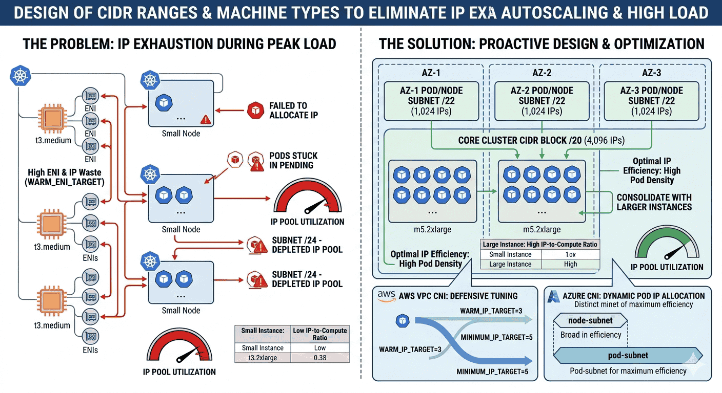
The Warm Pool Trap (WARM_ENI_TARGET & WARM_IP_TARGET): By default, the AWS VPC CNI allocates an entire secondary ENI full of IP addresses to a node as soon as a single Pod exceeds the capacity of the primary ENI. If your configuration parameters are set loosely, a node running just 5 Pods might aggressively hoard 30 IP addresses out of your subnet, causing massive artificial IP starvation across the wider cluster.
Azure CNI: Dynamic vs. Traditional Allocation
In standard Azure CNI topologies, IP allocation is predefined during the cluster or node-pool provisioning phase. You define a metric—historically defaulting to 30 Pods per node up to a maximum limit of 250. Upon node startup, Azure pre-allocates and locks that exact number of IPs from your VNet subnet to that specific virtual machine scale set (VMSS) instance, regardless of whether the node is running 1 Pod or 30 Pods. This rigid architecture makes careful upfront calculation absolutely vital.
3. The Machine Type Matrix: Balancing Compute vs. IP Density
Choosing the wrong machine types can inadvertently accelerate IP exhaustion. Selecting small, lightweight instances (e.g., `t3.medium` or `Standard_B2s`) to execute microservices results in a highly unfavorable IP-to-Compute Ratio. Let's evaluate how instance sizing alters network footprint requirements during peak auto-scaling windows:
| Cloud Provider | Instance Type / Size | vCPUs | RAM (GiB) | Max ENIs | IPs per ENI | Theoretical Max Pod IPs | Effective IP Footprint |
|---|---|---|---|---|---|---|---|
| AWS | t3.medium | 2 | 4 | 3 | 6 | 17 | 18 (High Waste Ratio) |
| AWS | m5.large | 2 | 8 | 3 | 10 | 29 | 30 |
| AWS | m5.2xlarge | 8 | 32 | 4 | 58 | 230 (Capped at 110) | 232 (Optimal Efficiency) |
| Azure | Standard_D2s_v5 | 2 | 8 | N/A | N/A | 30 (Configured) | 31 (1 Host + 30 Pods) |
| Azure | Standard_D8s_v5 | 8 | 32 | N/A | N/A | 30 (Configured) | 31 (1 Host + 30 Pods) |
The Design Strategy: Consolidate with Larger Instances
If your workload consists of memory-bound microservices allocated 0.5 vCPU and 1 GiB of RAM, scaling out using `t3.medium` instances means that to run 60 Pods, you will require roughly 4 nodes. These 4 nodes will absorb 72 IP addresses from your network subnet. Conversely, if you transition to a larger footprint like the `m5.2xlarge` (8 vCPU, 32 GiB RAM), a single instance can comfortably sustain all 60 Pods within its resource envelope. By consolidating onto a single larger node, your absolute IP overhead drops from 72 down to a clean, single-node allocation model. For high-density, horizontal workloads, leveraging larger instance tiers significantly buffers your subnet against rapid IP depletion during burst autoscale events.
4. Designing the Perfect CIDR Layout
When engineering an enterprise network architecture from scratch, always implement a strict, tiered hierarchy that factors in high-availability multi-AZ distribution, separate network tiers, and future horizontally-scaled auto-scaling margins.
The Production Calculation Workflow
Let's map out a production design scenario for a business-critical microservice cluster: Target Capacity: 1,500 active application Pods running concurrently during peak promotional windows. High Availability Blueprint: Uniform distribution across 3 Availability Zones (AZs). Autoscaling Buffer Factor: A standard 100% overhead margin (x2) to safely handle rolling, blue-green deployment pipelines, canary promotions, and emergency traffic spikes without network contention.
Applying our engineering logic across the multi-AZ topology: Total Target Pod Capacity = 1,500 * 2 = 3,000 Pod IPs Required. Per-AZ Pod Subnet Allocation = 3,000 / 3 = 1,000 IPs Minimum Per Zone. To safely accommodate a minimum of 1,000 IP addresses per Availability Zone, a network engineer must provision a `/22` block per subnet (which yields 1,022 usable host addresses after account reservations). Aggregating three individual `/22` regional subnets together dictates that the foundational VPC/VNet cluster network block must span a minimum size of `/20` (yielding 4,096 total usable IPs).
Enterprise Multi-AZ CIDR Allocation Architecture:==================================================Overall VPC/VNet Core Range: 10.100.0.0/16 (65,536 IPs)Dedicated Cluster CIDR Block: 10.100.0.0/20 (4,096 IPs)Subnet Distribution Matrix:├── AZ-1 Pod/Node Subnet: 10.100.0.0/22 (1,024 IPs) [Usable: 10.100.0.1 - 10.100.3.254]├── AZ-2 Pod/Node Subnet: 10.100.4.0/22 (1,024 IPs) [Usable: 10.100.4.1 - 10.100.7.254]└── AZ-3 Pod/Node Subnet: 10.100.8.0/22 (1,024 IPs) [Usable: 10.100.8.1 - 10.100.11.254]Reserved for Future Growth: 10.100.12.0/22 (1,024 IPs)5. Advanced DevOps Mitigations & Production Optimizations
If you are bound to an existing corporate network with severe IP restrictions and cannot assign broad `/20` address ranges, implement these enterprise engineering solutions to confidently mitigate IP exhaustion risks:
Optimization 1: Fine-Tune Environment Variables on AWS VPC CNI
Do not accept the default out-of-the-box CNI caching configurations. Apply defensive tuning properties directly inside your `aws-node` DaemonSet configuration manifest to limit aggressive background IP hoarding:
apiVersion: apps/v1kind: DaemonSetmetadata: name: aws-node namespace: kube-systemspec: template: spec: containers: - name: aws-node env: - name: WARM_IP_TARGET value: "3" - name: MINIMUM_IP_TARGET value: "5" - name: WARM_ENI_TARGET value: "0"Operational Impact: Setting `WARM_ENI_TARGET=0` commands the plugin to cease pre-allocating whole backup network interfaces. Setting `WARM_IP_TARGET=3` ensures that individual worker nodes only request 3 unallocated backup IP addresses above their current runtime needs, preserving the remaining shared subnet pool for other horizontal scaling events.
Optimization 2: AWS Custom Networking (Secondary Pod CIDR)
When your primary VPC subnet is completely depleted of addresses, you can configure EKS Custom Networking. This separates host node IPs from Pod IPs entirely. Nodes continue running on your restricted, corporate primary subnet (e.g., `10.0.0.0/24`), while the VPC CNI attaches secondary ENIs to Pods out of a completely separate, non-routable secondary internal RFC 1918 or CGNAT CIDR range attached to your VPC (such as `100.64.0.0/10`).
Optimization 3: Transition to Azure CNI with Dynamic Pod IP Allocation
For modern Azure deployments, migrate away from traditional Static Azure CNI and build your node pools using Dynamic Pod IP Allocation. With this feature enabled, you construct two distinct subnets inside your VNet:
Node-subnet: A highly compact, small-scale CIDR block (e.g., `/26`) explicitly dedicated to hosting only node VM system interfaces.
Pod-subnet: A broad, high-capacity, dedicated CIDR block (e.g., `/21`) mapped to your microservices.
During auto-scaling events, instead of locking large chunks of addresses down to individual VMs at boot time, IPs are dynamically allocated from the `pod-subnet` directly to Pod instances on an as-needed basis, yielding nearly 100% network usage efficiency.
6. The DevOps Post-Deployment Validation Checklist
Before launching any production workloads into a newly provisioned cluster, run through this verification pipeline to ensure the system is completely resilient to IP address exhaustion:
1. Verify the Node IPAM Configuration: Run `kubectl describe daemonset aws-node -n kube-system` and validate that the environment variables (`WARM_IP_TARGET`) align with your specific compute density targets.
2. Simulate Peak Scalability Constraints: Use a resource-intensive load testing utility (such as K6 or Locust) combined with a temporary deployment configuration set to a high replica count (e.g., `kubectl scale deployment load-test-app --replicas=500`). Monitor the scheduling timeline to verify that all Pods transition to a healthy `Running` state smoothly without network timeouts.
3. Configure Cloud Observability Alarms: Set up Amazon CloudWatch or Azure Monitor metric alerts targeting subnet utilization thresholds. Configure high-priority notifications to trigger whenever the `AvailableIpAddresses` pool metric falls below 20% of total capacity.
Conclusion
Preventing network IP exhaustion is an exercise in proactive capacity planning and strategic configuration. By selecting high-density compute nodes, building robust CIDR boundaries, and configuring cloud network plugins defensively, you ensure your infrastructure seamlessly adapts during peak traffic windows without suffering catastrophic network failures. Build defensively, double-check your network allocations, and let your clusters scale cleanly.